Table of Contents
Raspi-PD Control Hat
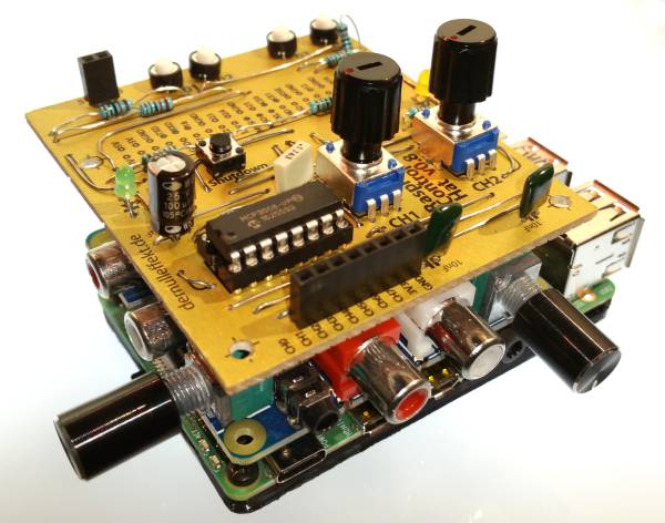
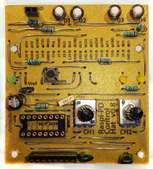
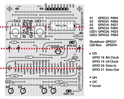
The Raspi-PD Control Hat is a physical interfacing board for the Raspberry Pi. It extend the GPIOs with 8 additional analog inputs, 4 push buttons and 2 indicator LEDs. It is based on the 10 bit analog to digital converter MCP3008. Two potentiometers are build in the board the other 6 inputs are free to use.
The Raspi-PD Control Hat was designed to use under Pure Data but could be controlled with the wiring library in C or python, too.
Pure Data (Pd) is a visual programming language developed by Miller Puckette.
Wiring for the Raspberry Pi was written by Gordon Henderson.
WiringPi for Pure Data was written by Miller Puckette, Jaime Oliver La Rosa and Jeremiah Rose.
The Raspi-PD Control Hat was used together with an Audio Injector. The manual for the installation one can find here:
Audio Injector Installation
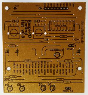
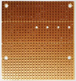
Paper PCB
Parts
- Resistors:
- 3x 1 kOhm
- 5x 10 kOhm
- Capacitors:
- 2x 10 nF
- 1x 100 nF
- 1x 100 µF
- Diodes:
- 3x LED
- Semiconductors
- 1x ADC MCP3008
- Mechanical:
- 1x IC socket, 16pins
- 1x pin strip 1×8
- 1x pin strip 1×2
- 5x push button
- Potentiometers:
- 2x 100 k
Software
Install Pure Data
Install some Externals
To install some Externals one can follow this manual:
http://dernulleffekt.de/doku.php?id=puredata:pduino#pure_data_and_pduino
Install Wiring
In the terminal:
$ sudo apt-get install wiringpi
For the Raspberry Pi 4 one needs to update the WiringPi to version 2.52:
 $ cd /tmp
 $ wget https://project-downloads.drogon.net/wiringpi-latest.deb
 $ sudo dpkg -i wiringpi-latest.deb
http://wiringpi.com/wiringpi-updated-to-2-52-for-the-raspberry-pi-4b/
Before using the WiringPi and the MCP 3008 enable the SPI interface in:
$ sudo raspi-config
Install the WiringPi for PD
Download: pd-wiringpi.zip.
Unzip and copy the wiringPi_gpio and the wiringPi_mcp3008 folder in the PD external folder.
/home/pi/Pd/externals
or do it in the terminal:
 $ wget http://www.dernulleffekt.de/programme/pd-wiringpi.zip
 $ unzip pd-wiringpi.zip
 $ cd pd-wiringpi/
 $ cp -R wiringPi_gpio/ /home/pi/Documents/Pd/externals/
 $ cp -R wiringPi_mcp3008/ /home/pi/Documents/Pd/externals/
One has to run Wiring PD with administration rights:
$ sudo pd
In Pure Data → Preferences → Path set the path to the two external folders. You might have to set the path for the PD folder, too. It should look like that.
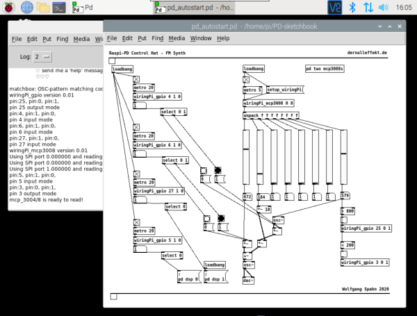
Here is an example patch for the Raspi-PD Control Hat FM-Synth
A more detailed manual for installing the PD wiring object on a Raspberry P 4 one finds here:
Wiring Pi for Pure Data
Connecting Sensors
For the analog inputs one can just connect any 5V source. And to get a smooth measurement one could put one capacitor between the ground and the measuring point as well as one between the power and the measuring point. For example two 1µF capacitors in a simple LDR resistor divider:
 GND---||---CH2---||----5V
             |
 GND---50k--------LDR---5V
or:
 CH2---------------In
      |       |
     100k    === 100nF
      |       |
     GND     GND
Install the Shutdown Button and the LED
Download the Python script:
$ wget http://www.dernulleffekt.de/programme/scripts.tar.xz
And unpack it:
$ tar -xf scripts.tar.xz
Go to in the script folder
$ cd /home/pi/scripts
Change owner & rights
$ sudo chown root:root shutdownbutton.py blink.py
$ sudo chmod 755 shutdownbutton.py blink.py
Create the autostart:
$ sudo nano /etc/rc.local
Write before “exit 0”:
# run reset and shutdown script and the blink script
printf ">>>>>>>> Starting shutdown aund reset button on GPIO 27 and a blinking LED on GPIO 04"
/home/pi/scripts/shutdownbutton.py &
/home/pi/scripts/blink.py &
To save and leave press: CTRL+O, Enter, CTRL+X
Reboot:
$ sudo reboot
Pin Assignment
For the buttons and the LEDs the following pins are used:
 Button/LED   GPIO    Wiring/PD
   01         23      04
   02         25      06
   03         16      27
   04         24      05
   LED1       26      25
   LED2       22      03
The MCP 3008 use these pins:
 MCP3008       Raspberry Pi
  CLK           SCLK (GPIO 11)
  DOUT          MISO (GPIO 09)
  DIN           MOSI (GPIO 10)
  CS/SHDN       CE0  (GPIO 08)
Links
https://www.open-electronics.org/discover-the-8-channnel-adc-8-expansion-shield/
MCP3008:
http://ww1.microchip.com/downloads/en/devicedoc/21295c.pdf
https://learn.adafruit.com/raspberry-pi-analog-to-digital-converters/mcp3008
GPIO:
https://www.raspberrypi.org/documentation/usage/gpio/
License
The Raspi-PD Control Hat was designed by Wolfgang Spahn 2020.
It is licensed under a Creative Commons Attribution-NonCommercial-ShareAlike 4.0 International License.

