Table of Contents
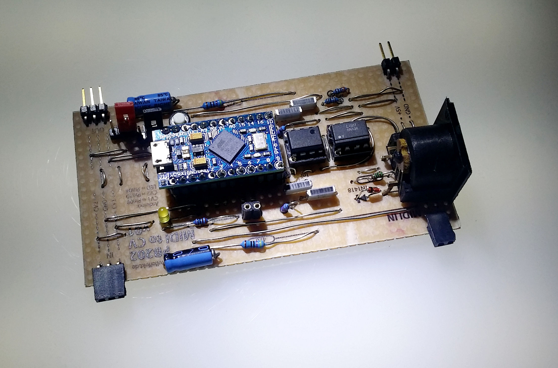
PB202 MIDI to CV
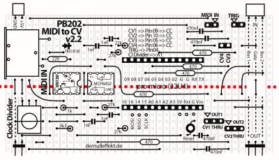
That MIDI and MIDI over USB board give four 0 to 5V output signals, CV1, CH2, CV3 and CV4. CV1 and CV2 are filtered.
The CCNumber are 1, 2, 3 and 4 on chanel 1. That can be easily modified in the code.
The board also outputs a trigger signal on an clock impulse. The poti is used as a clock divider.
For uploading code on the Arduino the Midi In jumper has to be off. One has to set the jumper for getting Midi in on the Arduino.
Paper-PCB
Software
Parts
- Resistors:
- 1x 220 Ohm
- 5x 470 Ohm
- 1x 1 kOhm
- 1x 3.3 kOhm
- 4x 27 KOhm
- Capacitors:
- 4x 1 nF
- 4x 470 nF
- Semiconductors:
- Arduino Pro Micro (Atmega 32U4)
- OpAmp MCP6002
- Optocoupler 6N138
- Diodes
- 1x 1N4148
- Potentiometer:
- 1x 100 kOhm
- Mechanical:
- 1x IC socket, 28 pin
- 2x IC socket, 8 pin
- 1x pin strip 1×10 pin
- 2x pin header, female 12 pin
- 2x pin header, female 90° 1×3, 1×2
- 2x pin header, male 90° 1×3, 1×2
- 2x push button
- 3x jumpers
License
The PB202 MIDI to CV was designed by Wolfgang Spahn, 2017-20.
It is licensed under a Creative Commons Attribution-NonCommercial-ShareAlike 4.0 International License.


