PB201 Step Sequencer
There is a new version of the sequencer use the PB206 Sequence (Total) Recall instead
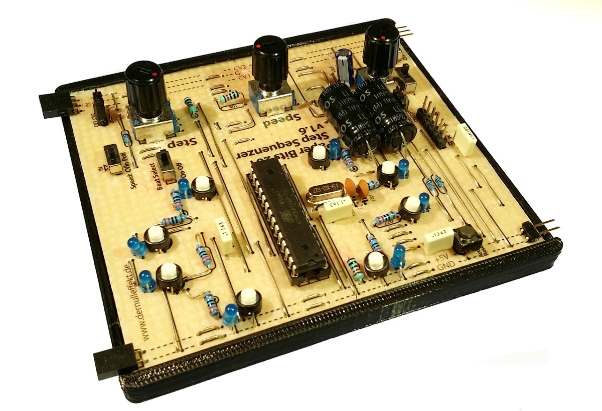
That is the 8 step sequencer for the Paper Bits. One can change steps, speed and the value of the CV output. To change to output for each step one select a value with the poti and in pressing the button for the step it will be asigned to it. The speed can be voltage controlled, too.
There are also 8 banks for storing notes and rhythm. In switching the preset on“ON” one can select them in pressing the “step buttons”. It is not longer possible to change speed, steps ore the CV until the switch is off again. To change the presets stored in the chip one can change the tables in the Arduino program.
If one has choosen one step then the speed poti can be used to select the individul step - voltage controlled with an LFO it will make some nice oscillation patter.
The board is based on an Arduino chip and therefore can be easily programmed and modified. One just need an USB to Serial converter or use an Arduino for that, too: The Arduino as a Serial Adapter.

Hardware
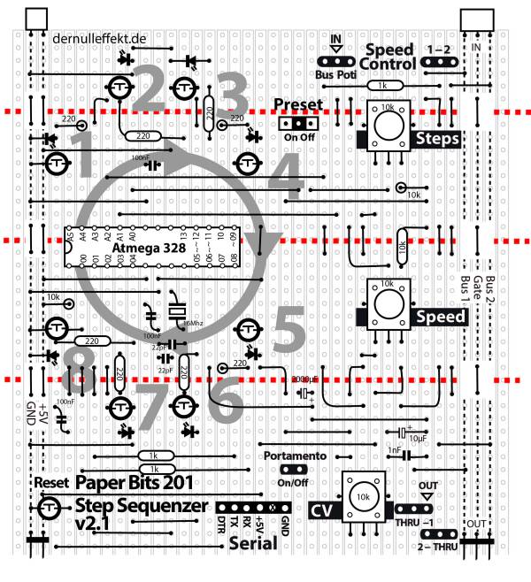
Paper-PCB
Parts
- Resistors:
- 8x 220 Ohm
- 3x 10 kOhm
- 3x 1 kOhm
- Capacitors:
- 2x 22 pF (ceramic)
- 3x 100 nF (foil)
- 1x 1 nF (foil)
- Electrolytic Capacitors:
- 1x 2200µF
- 1x 10 µF
- Diodes:
- 8x LEDs 3mm
- Crystal:
- 1x 16 Mhz
- IC:
- Atmega328P-PU
- Mechanical:
- 1x 28pin IC socket
- 1x pin strip 1×14
- 2x pin header, female 90° 1×3, 1×2
- 2x pin header, male 90° 1×3, 1×2
- 9x push buttons (2 pins)
- 1x mini switch
- 5x jumpers
- Potentiometers:
- 3x 10k
Software
Once you're board is ready, you will need to burn the arduino UNO bootloader on the chip (some chips are already burned from factory).
Follow the instructions:
burn the bootloader
Insert the chip into the IC socket and connect it to you're computer using a USB to Serial board.
breakout board
more about arduino pro mini
Or use your Arduino for that:
http://paperpcb.dernulleffekt.de/doku.php?id=arduino_clones:serial_adapter
Open the Arduino software on your computer and upload the following code to the board:
step_test_programm_01.zip
That is a test program to check if the voltage devider for the switch and the step poti has the right value.
Upload it to your board. Make shure the “beat select” button is off (should be to the right). Open the serial monitor on the Arduino IDE. When you turn the “step” poti the values should be between 0 and a certain maximum - and that is your important value (in my case 338)!
It could look like that:\
Step Poti = 250  Steps = 5
Step Poti = 250  Steps = 5
Step Poti = 250  Steps = 5
Step Poti = 338  Steps = 8
Step Poti = 338  Steps = 8
Step Poti = 338  Steps = 8
...
When you put a bit less than your maximum value in the code for the StepMax (for example 330) the “Steps” should be between 0 and 8 depending on the rotation of the potentiometer.
If you found the right value copy-paste that into the sequencer program, too and upload that to your board.
paperbits_stepsequenzer_62.zip
and voila!
License
The PB201 Step Sequencer was designed by Wolfgang Spahn, 2017-19.
It is licensed under a Creative Commons Attribution-NonCommercial-ShareAlike 4.0 International License.


